Evolution of treatment planning techniques in external-beam radiation therapy for head and neck cancer
Images


Radiation therapy is a standard therapeutic option for many patients with head and neck cancer (HNC) but presents many technical challenges. Primary head and neck tumors are often situated in close proximity to numerous critical structures, and delivering an ade quate radiation dose to the primary and regional lymph nodes requires special attention to protect these organs at risk (OARs). The treatment planning methods for HNC using external-beam radiotherapy have evolved from the traditional three-field technique in the early days to intensity-modulated radiotherapy (IMRT), and recently to the more efficient volumetric modulated arc therapy (VMAT). IMRT and VMAT require higher precision and accuracy in patient setup than conventional radiotherapy due to a highly conformal dose distribution and steep dose gradients. Thus, image guidance for head and neck radiotherapy has also evolved from weekly 2D portal imaging to daily 3D CT or cone-beam CT (CBCT) imaging. The rapid advancement in image-guided radiotherapy (IGRT) further allows the development of adaptive radiation therapy (ART). The purpose of this article is to review the technical evolution of treatment planning and delivery for HNC.
Three-field technique
Head and neck tumors are most commonly treated with 6 MV photon beams. The three-field technique consists of 2 opposed lateral fields to irradiate the primary tumor and cervical lymph nodes in the upper and lower neck, and a third anterior field to irradiate the supraclavicular lymph nodes. The bilateral fields and the anterior field share the same isocenter and are matched at the isocenter plane to avoid field overlaps at the field junction line. It is also desirable to move the junction line during the treatment course to feather the junction dose distribution.
The three-field technique involves multiple sequential boosts, with several prescriptions associated with each plan. Figure 1 shows the beam’s eye view (BEV) of a series of three-field plans with sequential cone-down boost fields. For this particular patient, the primary tumor and the upper neck nodal regions were treated to 72 Gy in 36 fractions (2 Gy/fx). The initial plan used the opposed lateral fields (Figure 1A) to irradiate the primary and upper neck nodal regions to 42 Gy. The lateral fields were then brought off the spinal cord through changing the blocks from 42 Gy to 54 Gy (Figure 1B). An additional cone-down of the lateral fields was performed from 54 Gy to 66 Gy to the primary tumor and the high-risk clinical target volume (CTV, Figure 1C), and again to the gross tumor volume (GTV) from 66 Gy to 72 Gy (Figure 1D). The supraclavicular region typically received 50 Gy in 25 fractions (2 Gy/fx) with an anterior field (Figure 1E). The middle block in Figure 1E was to protect the larynx. To further protect the spinal cord, the midline block was extended to the entire field as shown in Figure 1F from 44 Gy to 50 Gy. For patients with the enlarged posterior neck nodes, lateral electron beams were added to treat the neck nodes from 54 Gy to 66 Gy. Figure 2 shows a typical dose distribution of the composite sequential boost plans. As shown from Figure 2, a large volume of normal tissue was irradiated to a high radiation dose, thus increasing treatment toxicities such as xerostomia.
Intensity-modulated radiation therapy (IMRT)
Unlike the three-field treatment planning technique, IMRT delivers nonuniform beams across the tumor through a sequence of field segments with varying intensities that, in sum, deliver the desired dose distribution. IMRT can generate a conformal dose distribution and has steep dose fall-off at the boundary between the tumor and the normal structures. IMRT enables dose-escalation without increasing toxicity to the critical organs, potentially improving the therapeutic ratio.1,2 HNC is the ideal disease site for IMRT due to the complex tumor shape, the large number of adjacent sensitive structures, and minimum organ motion in the region.3-5 Furthermore, the ability of IMRT to produce inhomogeneous dose distribution allows the primary and secondary target volumes to be treated simultaneously.
Head and neck IMRT planning techniques include the split-field and the extended-field IMRT techniques.6-9 For the split-field IMRT technique, the primary and the upper neck above the vocal cords are treated with IMRT, and the lower neck and the supraclavicular fossae are treated with the conventional anterior field. The IMRT fields are matched with the anterior field at the isocenter with a half-beam block technique. One concern of the split-field technique is the possible underdosage of the tumor at the field junction.10 Alternatively, extended-field IMRT treats all tumor volumes simultaneously with different prescription doses to the primary tumor and the regional lymph nodes. This technique avoids field matching as in the split-field technique, but may increase the dose to the larynx if a special dose constraint is not applied to protect the larynx.9,11 The extended-field technique can also deliver a high dose to any involved lymph nodes in the lower neck and supraclavicular region.
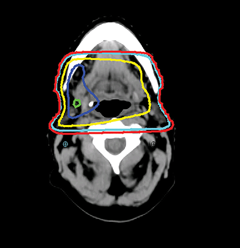
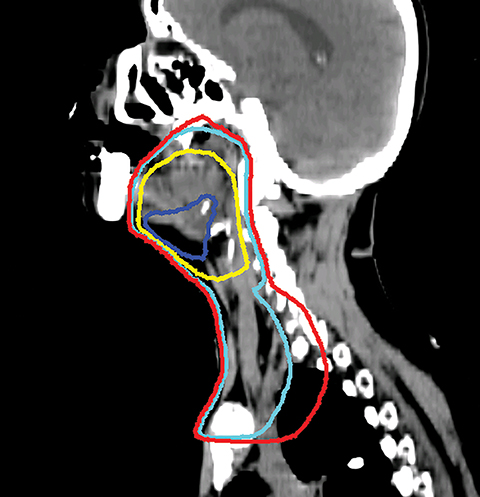
The GTV is defined as the gross extent of the primary tumor and any cervical lymph nodes felt to be involved on imaging or physical examination. The clinical target volume (CTV) is defined as the GTV plus a margin for potential microscopic spread of disease as well as the clinically negative but at-risk regional lymph nodes. As suggested by international guideline statements, intravenous contrast should be administered during the simulation scan to ensure accurate delineation of the GTV and cervical nodal levels.12 The planning target volume (PTV) is defined as the CTV plus a margin, usually 3-5 mm, depending on the image-guidance techniques used and the frequency of image guidance applied, to account for setup uncertainties. At Cleveland Clinic, we use daily kilovoltage or megavoltage cone-beam CT to correct for daily patient setup.
When planning, fusion of an18F-fluorodeoxyglucose positron emission tomography (18FDG-PET) with the treatment planning CT helps the delineation of the GTV. Studies have shown that PET-based delineation may lead to a significantly smaller GTV compared to CT-based delineation.13-15 However, interobserver variation in target-volume delineation remains an important source of uncertainty during IMRT planning. Continuing efforts had been made to generate consensus guidelines for the delineation of the neck node levels in node negative, node positive, and the postoperative neck regions.16
The typical beam arrangement for the treatment of bilateral tumors consists of 9 coplanar 6 MV photon beams evenly distributed around the patient (0°, 40°, 80°, 120°, 160°, 200°, 240°, 280°, and 320°). The typical beam arrangement for the treatment of unilateral cases consists of 7 coplanar beams, angled from the tumor side. The gantry angle should avoid the lateral directions and can be adjusted slightly to avoid the shoulder or to minimize the beam path through the shoulder. Given that the field size is often relatively large for head and neck treatments, the isocenter is usually selected at the center of the irradiated region.
The general planning goal is that at least 95% of the PTV and 99% of the CTV receive the prescription dose. The plan uniformity, defined as the ratio of the maximum dose (to 0.03 cc) of the plan to the highest prescription dose, should be limited within 115%. Table 1 lists the typical dose constraints of OARs clinically acceptable in our institution. These constraints, however, are highly variable based on the individual case.
IMRT optimization has evolved from forward planning in the early days to inverse planning currently used by the majority of treatment planning systems. Forward planning uses the field-in-field technique to achieve a simple intensity-modulated dose distribution.17,18 With forward planning, a planner manually adjusts the block shape and the beam intensity of each field through a trial-and-error process. Alternatively, inverse planning is a computer algorithm that adjusts the beam weighting and blocking to achieve an optimal plan based on dose objectives applied to the tumor targets and critical organs. Compared with forward planning, the inverse planning technique provides more conformal-dose distributions to the tumor volumes with significantly better sparing of critical structures.19-24 However, care must be taken as marginal failure in the spared parotid gland has been reported due to potentially inadequate dose to possible microscopic disease.25
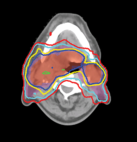
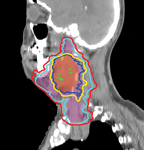
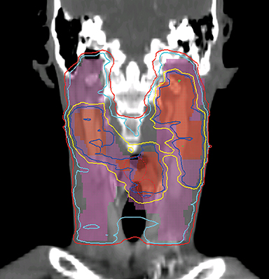
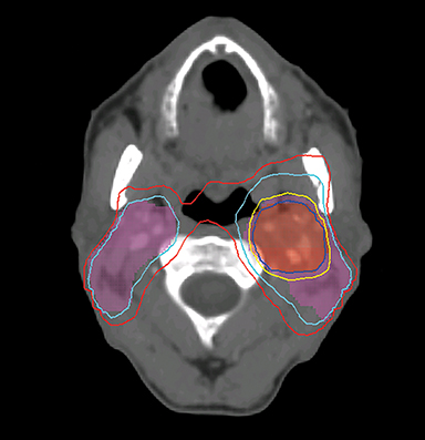
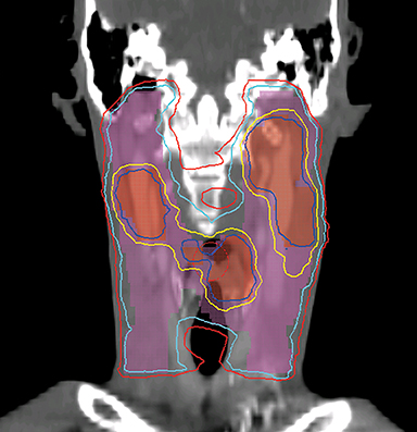
Even with computer optimization, IMRT planning for HNC is not a simple process. The most important task is the delineation of the tumor volumes and OARs. As listed in Table 1, some OARs are bilateral, resulting in more than 20 OARs to be outlined and evaluated for dose tolerance. Another key step is to define planning objectives for the targets and OARs during optimization, which can be specified as desired and displayed on a simplified dose volume histogram (DVH). For example, the dose coverage to the tumor target is often achieved by setting the maximum and minimum doses to the PTV, and the percentage of the PTV receiving the prescription dose. The maximum dose is usually the constraint of choice for serial OARs such as the spinal cord, while a mean dose or DVH-based planning objective is the constraint of choice for parallel OARs such as the salivary glands. Mean or DVH-based constraints allow a part of the parallel structures to receive a high dose in order to deliver a prescribed dose to the adjacent tumor volumes. By increasing the relative weight assigned to a particular planning objective, one can increase the probability of meeting a specific planning objective. Therefore, IMRT planning for HNC becomes an iterative process, involving multiple manual adjustments in the planning objectives according to the result of previous optimization. Frequently, planners also need to add artificial tuning structures to steer the optimizer to produce a plan that meets clinical requirements. Figure 3 shows a typical dose distribution for a nine-field IMRT plan, which is more conformal than that of the conventional three-field plan in Figure 2.
This process, which requires manual intervention, is partly due to the design of IMRT optimization. Most commercial IMRT treatment planning systems use a gradient-based optimization method. With this method, the solution obtained from the initial IMRT optimization is often not optimal because the optimizer may be trapped in a so-called “local minimum.” Therefore, to escape the local minimum and find an optimal solution, manual adjustments of the planning objectives are necessary. The limitation of this optimization method is one of the compounding factors contributing to the large variations in IMRT plan quality.
Volumetric-modulated arc therapy (VMAT)
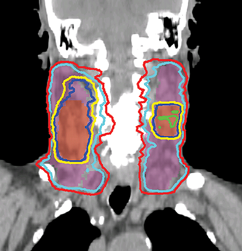
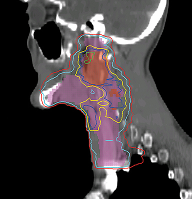
VMAT is an advanced form of IMRT. With a number of fixed gantry angles, the conventional IMRT plan delivers a number of small fields (segments) formed by the multileaf collimator (MLC) either by sequentially moving the MLC leaves to various positions and then delivering the radiation dose (step-and-shoot method), or by continuously moving the leaves during the beam-on time (sliding window method). VMAT delivery allows motion of the MLC and gantry while simultaneously adjusting MLC leaf speed, gantry speed, and dose rate while the radiation beam is on.26,27 VMAT has emerged as a mainstream treatment option for HNC.28 Given the complexity of the anatomy in the head and neck region, a VMAT plan usually consists of 2-3 full or partial arcs, depending on whether the treatment targets are bilateral or unilateral. VMAT plans increase the number of beam angles, and are therefore capable of creating a more conformal dose distribution to the target volume when compared to traditional IMRT. VMAT plans provide similar PTV coverage as the fixed gantry IMRT plans with improved homogeneity.29-31 Most importantly, the delivery time for a VMAT plan is much shorter (about 5 minutes) than that of a fixed gantry IMRT plan (10-15 minutes).31,32 Figure 4 compares the dose distributions from a two-arc VMAT plan and a nine-beam IMRT plan for a larynx cancer case with bilateral cervical lymph node involvement. The doses prescribed to the PTV of the primary tumor and elective LN are 70 Gy and 56 Gy in 35 fractions, respectively. Both VMAT and IMRT achieved adequate PTV dose coverage. The degree of OAR sparing is comparable for VMAT and IMRT,29,30 although occasionally the contralateral OAR sparing may be improved with VMAT.33
Image-guided radiation therapy (IGRT) for HNC
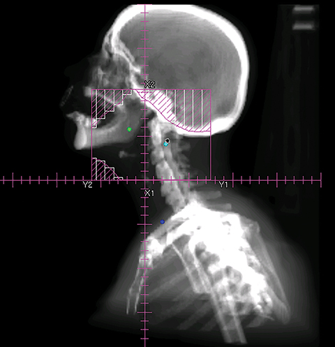
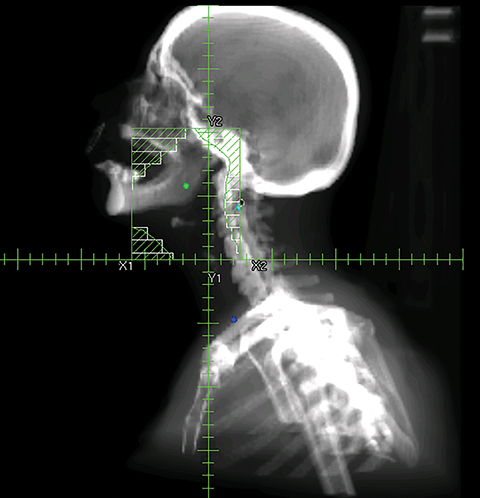
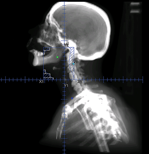
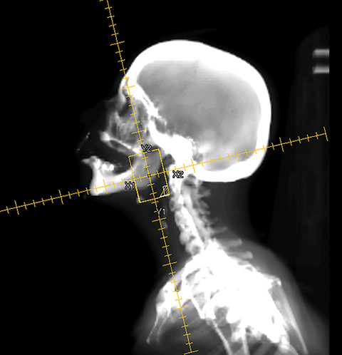
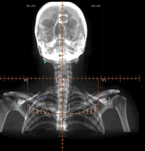
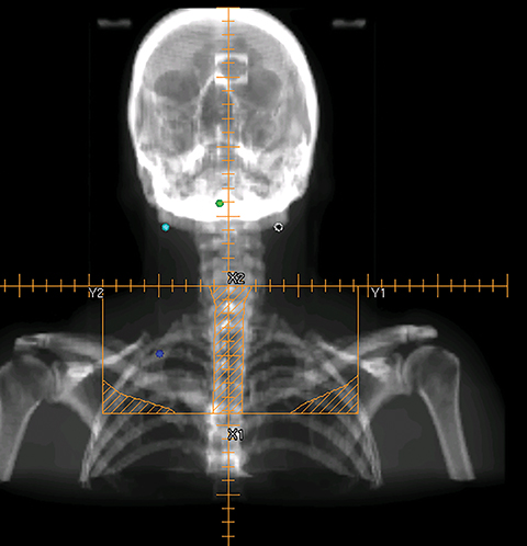
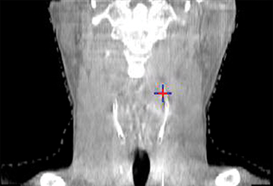
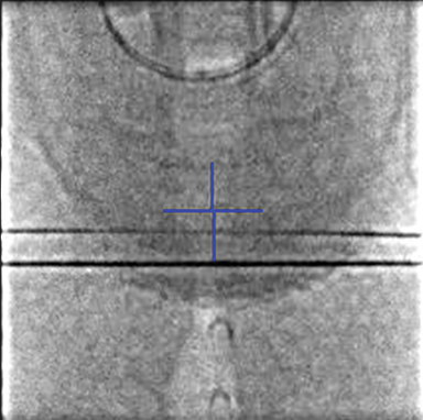
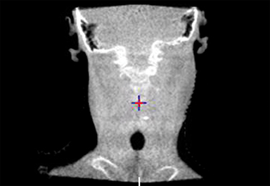
To improve the precision and accuracy of treatment delivery, IGRT uses various imaging techniques immediately before treatment to verify correct patient positioning. A conventional method to verify patient positioning is to match 2D kilovoltage (kV) or megavoltage (MV) radiographs with the digital reconstructed radiographs (DRRs) from the planning CT. As shown in Figure 5A and 5C, bony anatomy can be visualized in 2D kV and MV radiographs, detecting large positioning errors. However, 2D radiographs have poor image quality and limited soft tissue visualization and are incapable of detecting rotational errors in patient positions.
Three-dimensional in-room imaging techniques, such as CT-on-rails, kV-CBCT, and MV-CBCT have improved the detection of treatment positioning errors. The CT-on-rails system connects a conventional CT scanner with a linear accelerator (linac) by sharing the same treatment table, which can be rotated 180 degrees to acquire a diagnostic quality CT before each treatment. Similarly, if a dedicated CT-on-rails system is not available, CBCT images can be acquired by the treatment portal (MV) or by an orthogonal kV source. Figure 5B and 5D show an example of kV-CBCT and MV-CBCT images for HNC patients. On the kV-CBCT image, both bony anatomy and some soft tissues are visible while only bony anatomy can be visualized on the MV-CBCT image. CBCT imaging has been routinely used for interfraction correction where image registration software is used to align the CBCT image taken prior to the treatment with the planning CT and applies table shifts accordingly. However, frequent CBCT imaging can add significant doses to the patient. Imaging doses ranging from 0.1 to 3.5 cGy for kV-CBCT and 3 to 10 cGy for MV-CBCT per acquisition have been reported in the literature.34
One additional advantage of adding image-guidance to conformal techniques such as IMRT or VMAT is the ability to reduce the planning margins, potentially decreasing treatment-related toxicities, such as xerostomia and mucositis. Chen et al showed that the CTV-to-PTV margin can be safely reduced from 5 mm to 3 mm because there were no differences in overall survival, locoregional control, and distant metastasis-free survival among HNC patients treated with either a 5-mm or 3-mm margin.35 Den et al demonstrated that daily IGRT allows a 50% reduction in CTV-to-PTV margin for HNC patients, which may potentially reduce unnecessary toxicity.36 Schwarz et al compared a margin-based non-IGRT approach with a margin-reduced IGRT approach for postoperative HNC patients.37 They found that although both approaches achieved sufficient CTV coverage, IGRT is dosimetrically beneficial for spinal cord sparing due to the reduced PTV margin.
Although IGRT for HNC appears beneficial, challenges remain. First, one size of the CTV-to-PTV margin may not be fit for the entire treatment course.36 Second, IGRT is unable to correct for nonrigid positional changes, such as neck flexion and shoulder rotation. Therefore, proper patient immobilization via a thermoplastic mask is critical. Five-point masks are used to stabilize the shoulders when the treatment area extends to lower neck and are necessary for nearly all head and neck cases. Third, aligning to different bony landmarks may result in different patient position corrections. Typically, cervical vertebrae 1 and 2 (C1-C2) have been suggested as a reference landmark for standardizing IGRT for head and neck IMRT.38 In our practice, the alignment focal landmark for HNC patients is patient-specific and is part of the written prescription.
Adaptive radiation therapy (ART)
For a typical treatment course of 6-7 weeks, IMRT plans with reduced planning margins that are designed based on the original planning CT may become inadequate, particularly for patients with bulky gross tumors that shrink during treatment, and for patients who have experienced significant weight loss.39-42 A companion article from our institution is focused on the topic of ART.43 Briefly, at our institution, ART is performed on a case-by-case basis for HNC patients with significant tumor volume reduction, or for patients who experience dramatic weight loss.
The process for replanning midtreatment is as follows: First, a second simulation CT (replanning CT) is acquired at the midcourse of treatment. To facilitate tumor volume and OAR delineation, the replanning CT is registered with the initial planning CT by aligning the bony anatomy near the gross tumor. Deformation of the original simulation CT is acceptable in this situation and may facilitate the recontouring process. After the initial contours are transferred from the initial planning CT to the replanning CT, they are manually edited by the radiation oncologists. The adaptive plan is computed and evaluated using the total prescription dose but then delivered with a reduced number of fractions to match the total dose originally intended. Both initial and adaptive plans are evaluated on the dosimetric criteria discussed above. A composite plan that includes the number of fractions from both plans can be created through either rigid or deformable image registration, although challenges exist with both. Because of anatomic changes, a composite plan generated through rigid image registration cannot take into account soft-tissue changes occurring between the two planning CTs. Although deformable image registration improves the evaluation of changes due to soft-tissue deformation, composite plans created this way also bear dose uncertainties related to the accuracy of the computer algorithm. Therefore, the dose distribution from the composite plans is most useful for evaluating OARs that do not change volume during the course of treatment.
Conclusion
Head and neck radiation therapy is considered one of the most technically challenging treatments in radiation oncology because of the number of targets with different dose prescriptions, the large treatment regions, complex patient anatomy and the surrounding OARs. Nowadays, IMRT and VMAT are the mainstream treatment planning and delivery options for HNC. The technologic advances in IGRT and ART make patient-specific radiotherapy plans possible and have led to the next stage of individualized radiation therapy.
References
- de Arruda FF, Puri, DR, Zhung J, et al. Intensity-modulated radiation therapy for the treatment of oropharyngeal carcinoma: the Memorial Sloan-Kettering Cancer Center expe rience. Int J Radiat Oncol Biol Phys. 2006;64(2):363-373.
- Lee N, Harris J, Garden AS, et al. Intensity-modulated radiation therapy with or without chemotherapy for nasopharyngeal carcinoma: radiation therapy oncology group phase II trial 0225. J Clin Oncol. 2009;27(22):3684-3690.
- Nutting C, Dearnaley DP, and Webb S. Intensity modulated radiation therapy: a clinical review. B J Radiol. 2000;73(869):459-469.
- Claus F, Duthoy W, Boterberg T, et al. Intensity modulated radiation therapy for oropharyngeal and oral cavity tumors: clinical use and experience. Oral Oncol. 2002;38(6):597-604.
- Hunt MA, Zelefsy MJ, Wolden S, et al. Treatment planning and delivery of intensity-modulated radiation therapy for primary nasopharynx cancer. Int J Radiat Oncol Biol Phys. 2001;49(3):623-632.
- Lee N, Xia P, Quivey JM, et al. Intensity-modulated radiotherapy in the treatment of nasopharyngeal carcinoma: an update of the UCSF experience. Int J Radiat Oncol Biol Phys. 2002;53(1):12-22.
- Lee N, Xia P, Fischbein NJ, et al. Intensity-modulated radiation therapy for head-and-neck cancer: the UCSF experience focusing on target volume delineation. Int J Radiat Oncol Biol Phys. 2003;57(1):49-60.
- Dabaja B, Salehpour MR, Rosen I, et al. Intensity-modulated radiation therapy (IMRT) of cancers of the head and neck: comparison of split-field and whole-field techniques. Int J Radiat Oncol Biol Phys. 2005;63(4):1000-1005.
- Lee N, Mechalakos J, Puri DR, Hunt M. Choosing an intensity-modulated radiation therapy technique in the treatment of head-and-neck cancer. Int J Radiat Oncol Biol Phys. 2007;68(5):1299-1309.
- Thorstad W, Hong S, Hope AJ, et al. Patterns of failure in patients receiving intensity modulated radiation therapy (IMRT) for head and neck cancer. Int J Radiat Oncol Biol Phys. 2005;63(2)[Suppl 1]:S74.
- Amdur RJ, Li JG, Liu C, et al. Unnecessary laryngeal irradiation in the IMRT era. Head Neck. 2004;26(3):257-263.
- Brouwer CL, Steenbakkers RJHM, Bourhis J, et al. CT-based delineation of organs at risk in the head and neck region: DAHANCA, EORTC, GORTEC, HKNPCSG, NCIC CTG, NCRI, NRG Oncology and TROG consensus guidelines. Radiother Oncol. 2015.
- Paulino AC, Koshy M, Howell R, et al. Comparison of CT- and FDG-PET-defined gross tumor volume in intensity-modulated radiotherapy for head-and-neck cancer. Int J Radiat Oncol Biol Phys. 2005;61(5):1385-1392.
- Delouya G, Igidbashian L, Houle A, et al. 18 F-FDG-PET imaging in radiotherapy tumor volume delineation in treatment of head and neck cancer. Radiother Oncol. 2011;101(3):362-368.
- Leclerc M, Lartigau E, Lacornerie T, et al. Primary tumor delineation based on (18)FDG PET for locally advanced head and neck cancer treated by chemo-radiotherapy. Radiother Oncol. 2015;116(1):87-93.
- Gregoire V, Ang K, Budach W, et al. Delineation of the neck node levels for head and neck tumors: a 2013 update. DAHANCA, EORTC, HKNPCSG, NCIC CTG, NCRI, RTOG, TROG consensus guidelines. Radiother Oncol. 2014;110(1): 172-181.
- Lee N, Akazawa C, Akazawa P, et al. A forward-planned treatment technique using multisegments in the treatment of head-and-neck cancer. Int J Radiat Oncol Biol Phys. 2004;59(2):584-594.
- Herrassi MY, Bentayeb F, Malisan MR. Comparative study of four advanced 3d-conformal radiation therapy treatment planning techniques for head and neck cancer. J Med Phys. 2013;38(2):98-105.
- Xia P, Fu KK, Wong GW, et al. Comparison of treatment plans involving intensity-modulated radiotherapy for nasopharyngeal carcinoma. Int J Radiat Oncol Biol Phys. 2000;48(2):329-337.
- Huang D, Xia P, Akazawa P, et al. Comparison of treatment plans using intensity-modulated radiotherapy and three-dimensional conformal radiotherapy for paranasal sinus carcinoma. Int J Radiat Oncol Biol Phys. 2003;56(1):158-168.
- Poon I, Xia P, Weinberg V, et al.A treatment planning analysis of inverse-planned and forward-planned intensity-modulated radiation therapy in nasopharyngeal carcinoma. Int J Radiat Oncol Biol Phys. 2007;69(5):1625-1633.
- Kam MKM, Leung SF, Zee B, et al. Prospective randomized study of intensity-modulated radiotherapy on salivary gland function in early-stage nasopharyngeal carcinoma patients. J Clin Oncol. 2007;25(31):4873-4879.
- Pow EH, Kwong DL, McMillan AS, et al. Xerostomia and quality of life after intensity-modulated radiotherapy vs. conventional radiotherapy for early-stage nasopharyngeal carcinoma: initial report on a randomized controlled clinical trial. Int J Radiat Oncol Biol Phys. 2006;66(4):981-991.
- Nutting CM, Morden JP, Harrington KJ, et al. Parotid-sparing intensity modulated versus conventional radiotherapy in head and neck cancer (PARSPORT): a phase 3 multicentre randomised controlled trial. Lancet Oncol. 2011;12(2):127-136.
- Cannon DM, Lee NY. Recurrence in region of spared parotid gland after definitive intensity-modulated radiotherapy for head and neck cancer. Int J Radiat Oncol Biol Phys. 2008;70(3):660-665.
- Yu, C.X. Intensity-modulated arc therapy with dynamic multileaf collimation: an alternative to tomotherapy. Phys Med Biol. 1995;40(9):1435-1449.
- Otto K. Volumetric modulated arc therapy: IMRT in a single gantry arc. Med Phys. 2008.35(1):310-317.
- Teoh M, Clark CH, Wood K, et al. Volumetric modulated arc therapy: a review of current literature and clinical use in practice. Br J Radiol. 2011;84(1007):967-996.
- Verbakel WF, Cuiipers JP, Hoffmans D, et al. Volumetric intensity-modulated arc therapy vs. conventional IMRT in head-and-neck cancer: a comparative planning and dosimetric study. Int J Radiat Oncol Biol Phys. 2009;74(1):252-259.
- Vanetti E, Clivio A, Nicolini G, et al. Volumetric-modulated arc radiotherapy for carcinomas of the oro-pharynx, hypo-pharynx and larynx: a treatment planning comparison with fixed field IMRT. Radiother Oncol. 2009;92(1):111-117.
- Rao M, Yang W, Chen F, et al. Comparison of Elekta VMAT with helical tomotherapy and fixed field IMRT: plan quality, delivery efficiency and accuracy. Med Phys. 2010;37(3):1350-1349.
- Stieler F, Wolff D, Schmid H, et al. A comparison of several modulated radiotherapy techniques for head and neck cancer and dosimetric validation of VMAT. Radiother Oncol. 2011;101(3):388-393.
- Johnston M, Clifford S, Bromley R, et al. Volumetric-modulated arc therapy in head and neck radiotherapy: A planning comparison using simultaneous integrated boost for nasopharynx and oropharynx carcinoma. Clin Oncol. 2011;23(8):503-511.
- Bissonnette JP, Balter PA, Dong L, et al. Quality assurance for image-guided radiation therapy utilizing CT-based technologies: a report of the AAPM TG-179. Med Phys. 2012; 39(4):1946-1963.
- Chen AM, Farwell DG, Luu Q, et al. Evaluation of the planning target volume in the treatment of head and neck cancer with intensity-modulated radiotherapy: what is the appropriate expansion margin in the setting of daily image guidance? Int J Radiat Oncol Biol Phys. 2011; 81(4):943-949.
- Den RB, Doemer A, Kubicek G, et al. Daily image guidance with cone-beam computed tomography for head-and-neck cancer intensity-modulated radiotherapy: a prospective study. Int J Radiat Oncol Biol Phys. 2010;76(5):1353-1359.
- Schwarz M, Giske K, Stoll A, et al. IGRT versus non-IGRT for postoperative head-and-neck IMRT patients: dosimetric consequences arising from a PTV margin reduction. Radiat Oncol. 2012;7:133.
- Graff P, Kirby N, Weinberg V, et al. The residual setup errors of different IGRT alignment procedures for head and neck IMRT and the resulting dosimetric impact. Int J Radiat Oncol Biol Phys. 2013. 86(1):170-176.
- Barker JL Jr, Garden AS, Ang KK, et al. Quantification of volumetric and geometric changes occurring during fractionated radiotherapy for head-and-neck cancer using an integrated CT/linear accelerator system. Int J Radiat Oncol Biol Phys. 2004;59(4):960-970.
- Vakilha M, et al. Changes in position and size of parotid glands assessed with daily cone-beam CT during image-guided IMRT for head and neck cancer: implications for dose received. Int J Radiat Oncol Biol Phys. 69(3):S438-S439.
- Lee C, Langen KM, Lu W, et al. Evaluation of geometric changes of parotid glands during head and neck cancer radiotherapy using daily MVCT and automatic deformable registration. Radiother Oncol. 2008;89(1):81-88.
- Wang ZH, Yan C, Zhang ZY, et al. Radiation-induced volume changes in parotid and submandibular glands in patients with head and neck cancer receiving postoperative radiotherapy: a longitudinal study. Laryngoscope. 2009;119(10):1966-1974.
- Juloori A, Ward MC, Joshi NP, et al. Adaptive radiation therapy for head and neck cancer. Applied Radiat Oncol. 2015;4(3):12-17.